
Download
In this example, the endpoint (EP) on the left initiated communication with the gateway on the right and the gateway connected the call with the called party. In reality, call flows are often more complex than the one shown, but most calls that utilize the Fast Connect procedures defined within H.323 can be established with as few as 2 or 3 messages. Endpoints must notify their gatekeeper (if gatekeepers are used) that they are in a call.
H.323 is a recommendation from the ITU Telecommunication Standardization Sector (ITU-T) that defines the protocols to provide audio-visual communication sessions on any packet network. The H.323 standard addresses call signaling and control, multimedia transport and control, and bandwidth control for point-to-point and multi-point conferences.
It is widely implemented by voice and videoconferencing equipment manufacturers, is used within various Internet real-time applications such as GnuGK and NetMeeting and is widely deployed worldwide by service providers and enterprises for both voice and video services over IP networks.
It is a part of the ITU-T H.32x series of protocols, which also address multimedia communications over ISDN, the PSTN or SS7, and 3G mobile networks.
H.323 call signaling is based on the ITU-T Recommendation Q.931 protocol and is suited for transmitting calls across networks using a mixture of IP, PSTN, ISDN, and QSIG over ISDN. A call model, similar to the ISDN call model, eases the introduction of IP telephony into existing networks of ISDN-based PBX systems, including transitions to IP-based PBXs.
Within the context of H.323, an IP-based PBX might be a gatekeeper or other call control element which provides service to telephones or videophones. Such a device may provide or facilitate both basic services and supplementary services, such as call transfer, park, pick-up, and hold.
(Note: Note Cisco IP phones do not support the H.323 protocol due to its excessive resource consumption.)
History
The most widely-adopted and hence most promising network infrastructure - and the one bearing the largest difficulties to achieve well-defined Quality of Service - was addressed in the beginning of 1995 in H.323: Local Area Networks, with the focus on IP as the network layer protocol.The primary goal was to interface multimedia communication equipment on LANs to the reasonably well-established base on circuit-switched networks.
The initial version of H.323 was approved by the ITU-T about one year later, in June 1996, thereby providing a base on which the industry could converge.The initial focus was clearly on local network environments, because QoS mechanisms for IP-based wide area networks, such as the Internet, were not well established at this point. In early 1996, Internet-wide deployment of H.323 was already explicitly included in the scope, as was the aim to support voice-only applications and, thus, the foundations to use H.323 for IP Telephony were laid. H.323 has continuously evolved towards becoming a technically sound and functionally rich protocol platform for IP Telephony applications.The first major additions to this end were included in H.323 version 2, approved by the ITU-T in January 1998. In September 1999, H.323v3 was approved by the ITU-T, incorporating numerous further functional and conceptual extensions to enable H.323 to serve as a basis for IP Telephony on a global scale and as well as making it meet requirements in enterprise environments. Moreover, many new enhancements were introduced into the H.323 protocol. Version 4 was approved on November 17, 2000 and contains enhancements in a number of important areas, including reliability, scalability, and flexibility.
New features help facilitate more scalable Gateway and MCU solutions to meet the growing market requirements. H.323 has been the undisputed leader in voice, video, and data conferencing on packet networks, and Version 4 endeavours to keep H.323 ahead of the competition.
H.323 was the first VoIP standard to adopt the Internet Engineering Task Force (IETF) standard Real-time Transport Protocol (RTP) to transport audio and video over IP networks.
Scope
The scope of H.323 encompasses multimedia communication in IP-based networks, with significant consideration given to gatewaying to circuit-switched networks (in particular to ISDN-based video telephony and to PSTN/ISDN/GSM for voice communication).
H.323 defines a number of functional / logical components as shown in Figure:
 |
| Scope and Components defined in H.323 |
- Terminal: Terminals are H.323-capable endpoints, which may be implemented in software on workstations or as stand-alone devices (such as telephones).They are assigned to one or more aliases (e.g. a user's name/URI) and/or telephone number(s);
- Gateway: Gateways interconnect H.323 entities (such as endpoints, MCUs, or other gateways) to other network/protocol environments (such as the telephone network).They are also assigned one or more aliases and/or telephone number(s).The H.323 Series of Recommendations provides detailed specifications for interfacing H.323 to H.320, ISDN/PSTN, and ATM-based networks. Recent work also addresses control and media gateway specifications for telephony trunking networks such as SS7/ISUP;
- Gatekeeper: The gatekeeper is the core management entity in an H.323 environment. It is, among other things, responsible for access control, address resolution and H.323 network (load) management and provides the central hook to implement any kind of utilisation / access policies. An H.323 environment is subdivided into zones (which may, but need not be congruent with the underlying network topology); each zone is controlled by one primary gatekeeper (with optional backup gatekeepers). Gatekeepers may also provide added value, e.g., act as a conferencing bridge or offer supplementary call services.An H.323 Gatekeeper can also be equipped with the proxy feature. Such a feature enables the routing through the gatekeeper of the RTP traffic (audio and video) and the T.120 traffic (data), so no traffic is directly exchanged between endpoints. (It could be considered a kind of IP-to-IP gateway that can be used for security and QoS purposes);
- Multipoint Controller (MC): A Multipoint Controller is a logical entity that interconnects the call signalling and conference control channels of two or more H.323 entities in a star topology. MCs coordinate the (control aspects of) media exchange between all entities involved in a conference.They also provide the endpoints with participant lists, exercise floor control, etc. MCs may be embedded in any H.323 entity (terminals, gateways gatekeepers) or implemented as stand-alone entities.They can be cascaded to allow conferences spanning multiple MCs;
- Multipoint Processor (MP): For multipoint conferences with H.323, an optional Multipoint Processor may be used that receives media streams from the individual endpoints, combines them through some mixing/switching technique, and transmits the resulting media streams back to the endpoints;
- Multipoint Control Unit (MCU): In the H.323 world, an MCU is simply a combination of an MC and an MP in a single device. The term originates in the ISDN videoconferencing world where MCUs were needed to create multipoint conferences out of a set of point-to-point connections.
Protocols
H.323 is a system specification that describes the use of several ITU-T and IETF protocols. The protocols that comprise the core of almost any H.323 system are:
- H.225.0 Registration, Admission and Status (RAS), which is used between an H.323 endpoint and a Gatekeeper to provide address resolution and admission control services.
- H.225.0 Call Signaling, which is used between any two H.323 entities in order to establish communication.
- H.245 control protocol for multimedia communication, which describes the messages and procedures used for capability exchange, opening and closing logical channels for audio, video and data, control and indications.
- Real-time Transport Protocol (RTP), which is used for sending or receiving multimedia information (voice, video, or text) between any two entities.
- Many H.323 systems also implement other protocols that are defined in various ITU-T Recommendations to provide supplementary services support or deliver other functionality to the user. Some of those Recommendations are:
- H.235 series describes security within H.323, including security for both signaling and media.
- H.239 describes dual stream use in videoconferencing, usually one for live video, the other for still images.
- H.450 series describes various supplementary services.
- H.460 series defines optional extensions that might be implemented by an endpoint or a Gatekeeper, including ITU-T Recommendations H.460.17, H.460.18, and H.460.19 for Network address translation (NAT) / Firewall (FW) traversal.
In addition to those ITU-T Recommendations, H.323 implements various IETF Request for Comments (RFCs) for media transport and media packetization, including the Real-time Transport Protocol (RTP).
Architecture
The H.323 system defines several network elements that work together in order to deliver rich multimedia communication capabilities. Those elements are Terminals, Multipoint Control Units (MCUs), Gateways, Gatekeepers, and Border Elements. Collectively, terminals, multipoint control units and gateways are often referred to as endpoints.
While not all elements are required, at least two terminals are required in order to enable communication between two people. In most H.323 deployments, a gatekeeper is employed in order to, among other things, facilitate address resolution.
 |
| A Complete & Sophisticated Protocol Stack |
H.323 Network Elements
Terminals
Terminals in an H.323 network are the most fundamental elements in any H.323 system, as those are the devices that users would normally encounter. They might exist in the form of a simple IP phone or a powerful high-definition videoconferencing system.
Inside an H.323 terminal is something referred to as a Protocol stack, which implements the functionality defined by the H.323 system. The protocol stack would include an implementation of the basic protocol defined in ITU-T Recommendation H.225.0 and H.245, as well as RTP or other protocols described above.
The diagram, figure, depicts a complete, sophisticated stack that provides support for voice, video, and various forms of data communication. In reality, most H.323 systems do not implement such a wide array of capabilities, but the logical arrangement is useful in understanding the relationships.
Multipoint Control Units
A Multipoint Control Unit (MCU) is responsible for managing multipoint conferences and is composed of two logical entities referred to as the Multipoint Controller (MC) and the Multipoint Processor (MP). In more practical terms, an MCU is a conference bridge not unlike the conference bridges used in the PSTN today. The most significant difference, however, is that H.323 MCUs might be capable of mixing or switching video, in addition to the normal audio mixing done by a traditional conference bridge. Some MCUs also provide multipoint data collaboration capabilities. What this means to the end user is that, by placing a video call into an H.323 MCU, the user might be able to see all of the other participants in the conference, not only hear their voices.
Gateways
Gateways are devices that enable communication between H.323 networks and other networks, such as PSTN or ISDN networks. If one party in a conversation is utilizing a terminal that is not an H.323 terminal, then the call must pass through a gateway in order to enable both parties to communicate.
Gateways are widely used today in order to enable the legacy PSTN phones to interconnect with the large, international H.323 networks that are presently deployed by services providers. Gateways are also used within the enterprise in order to enable enterprise IP phones to communicate through the service provider to users on the PSTN.
Gateways are also used in order to enable videoconferencing devices based on H.320 and H.324 to communicate with H.323 systems. Most of the third generation (3G) mobile networks deployed today utilize the H.324 protocol and are able to communicate with H.323-based terminals in corporate networks through such gateway devices.
Gatekeepers
A Gatekeeper is an optional component in the H.323 network that provides a number of services to terminals, gateways, and MCU devices. Those services include endpoint registration, address resolution, admission control, user authentication, and so forth. Of the various functions performed by the gatekeeper, address resolution is the most important as it enables two endpoints to contact each other without either endpoint having to know the IP address of the other endpoint.
Gatekeepers may be designed to operate in one of two signaling modes, namely "direct routed" and "gatekeeper routed" mode. Direct routed mode is the most efficient and most widely deployed mode. In this mode, endpoints utilize the RAS protocol in order to learn the IP address of the remote endpoint and a call is established directly with the remote device. In the gatekeeper routed mode, call signaling always passes through the gatekeeper. While the latter requires the gatekeeper to have more processing power, it also gives the gatekeeper complete control over the call and the ability to provide supplementary services on behalf of the endpoints.
H.323 endpoints use the RAS protocol to communicate with a gatekeeper. Likewise, gatekeepers use RAS to communicate with other gatekeepers.
A collection of endpoints that are registered to a single Gatekeeper in H.323 is referred to as a “zone”. This collection of devices does not necessarily have to have an associated physical topology. Rather, a zone may be entirely logical and is arbitrarily defined by the network administrator.
Gatekeepers have the ability to neighbor together so that call resolution can happen between zones. Neighboring facilitates the use of dial plans such as the Global Dialing Scheme. Dial plans facilitate “inter-zone” dialing so that two endpoints in separate zones can still communicate with each other.
Border Elements and Peer Elements
Border Elements and Peer Elements are optional entities similar to a Gatekeeper, but that does not manage endpoints directly and provide some services that are not described in the RAS protocol. The role of a border or peer element is understood via the definition of an "administrative domain".
An administrative domain is the collection of all zones that are under the control of a single person or organization, such as a service provider. Within a service provider network there may be hundreds or thousands of gateway devices, telephones, video terminals, or other H.323 network elements. The service provider might arrange devices into "zones" that enable the service provider to best manage all of the devices under its control, such as logical arrangement by city. Taken together, all of the zones within the service provider network would appear to another service provider as an "administrative domain".
 |
| An illustration of an administrative domain with border elements, peer elements, and gatekeepers |
The border element is a signaling entity that generally sits at the edge of the administrative domain and communicates with another administrative domain. This communication might include such things as access authorization information; call pricing information; or other important data necessary to enable communication between the two administrative domains.
Peer elements are entities within the administrative domain that, more or less, help to propagate information learned from the border elements throughout the administrative domain. Such architecture is intended to enable large-scale deployments within carrier networks and to enable services such as clearinghouses.
H.323 Network Signaling
H.323 is defined as a binary protocol, which allows for efficient message processing in network elements. The syntax of the protocol is defined in ASN.1 and uses the Packed Encoding Rules (PER) form of message encoding for efficient message encoding on the wire. Below is an overview of the various communication flows in H.323 systems.
H.225.0 Call Signaling
The call signalling channel is used to signal call setup intention, success, failures, etc, as well as to carry operations for supplementary services. Call signalling messages are derived from Q.931 (ISDN call signalling); however, simplified procedures and only a subset of the messages are used in H.323.The call signalling channel is used end-to-end between calling party and called party and may optionally run through one or more gatekeepers.
Once the address of the remote endpoint is resolved, the endpoint will use H.225.0 Call Signaling in order to establish communication with the remote entity. H.225.0 messages are:
- Setup and Setup acknowledge
- Call Proceeding
- Connect
- Alerting
- Information
- Release Complete
- Facility
- Progress
- Status and Status Inquiry
- Notify
Optimisations: Since version 3, H.225.0 supports the following enhancements:
- Multiple Calls: To prevent using a dedicated TCP connection for each call, gateways can be built to handle multiple calls on each connection.
- Maintain Connection: Similar to Multiple Calls, this enhancement will reduce the need to open new TCP connections.After the last call has ended, the endpoint may decide to maintain the TCP connection to provide a better call setup time for the next call.
In the simplest form, an H.323 call may be established as follows.
 |
| Establishment of an H.323 Call |
Once a call has concluded, a device will send a Release Complete message. Endpoints are then required to notify their gatekeeper (if gatekeepers are used) that the call has ended.
H.225.0 Registration, Admission and Status (RAS) Signaling
The RAS channel is used for communication between H.323 endpoints and their gatekeeper and for some inter-gatekeeper communication. Endpoints use RAS to register with their gatekeeper, to request permission to utilise system resources, to have addresses of remote endpoints resolved, etc. Gatekeepers use RAS to keep track of the status of their associated endpoints and to collect information about actual resource utilisation after call termination. RAS provides mechanisms for user/endpoint authentication and call authorisation.
RAS is a fairly simple protocol composed of just a few messages. Namely:
 |
| A high-level communication exchange between two endpoints (EP) and two gatekeepers (GK) |
- Gatekeeper request, reject and confirm messages (GRx)
- Registration request, reject and confirm messages (RRx)
- Unregister request, reject and confirm messages (URx)
- Admission request, reject and confirm messages (ARx)
- Bandwidth request, reject and confirm message (BRx)
- Disengage request, reject and confirm (DRx)
- Location request, reject and confirm messages (LRx)
- Info request, ack, nack and response (IRx)
- Nonstandard message
- Unknown message response
- Request in progress (RIP)
- Resource availability indication and confirm (RAx)
- Service control indication and response (SCx)
When an endpoint is powered on, it will generally send a gatekeeper request (GRQ) message to "discover" gatekeepers that are willing to provide service. Gatekeepers will then respond with a gatekeeper confirm (GCF) and the endpoint will then select a gatekeeper to work with. Alternatively, it is possible that a gatekeeper has been predefined in the system’s administrative setup so there is no need for the endpoint to discover one.
Once the endpoint determines the gatekeeper to work with, it will try to register with the gatekeeper by sending a registration request (RRQ), to which the gatekeeper responds with a registration confirm (RCF). At this point, the endpoint is known to the network and can make and place calls.
When an endpoint wishes to place a call, it will send an admission request (ARQ) to the gatekeeper. The gatekeeper will then resolve the address (either locally, by consulting another gatekeeper, or by querying some other network service) and return the address of the remote endpoint in the admission confirm message (ACF). The endpoint can then place the call.
Upon receiving a call, a remote endpoint will also send an ARQ and receive an ACF in order to get permission to accept the incoming call. This is necessary, for example, to authenticate the calling device or to ensure that there is available bandwidth for the call.
H.245 Call Control
Once a call has initiated (but not necessarily fully connected) endpoints may initiate H.245 call control signaling in order to provide more extensive control over the conference. H.245 is a rather voluminous specification with many procedures that fully enable multipoint communication, though in practice most implementations only implement the minimum necessary in order to enable point-to-point voice and video communication.
H.245 provides capabilities such as capability negotiation, master/slave determination, opening and closing of "logical channels" (i.e., audio and video flows), flow control, and conference control. It has support for both unicast and multicast communication, allowing the size of a conference to theoretically grow without bound.
Capability Negotiation
Of the functionality provided by H.245, capability negotiation is arguably the most important, as it enables devices to communicate without having prior knowledge of the capabilities of the remote entity. H.245 enables rich multimedia capabilities, including audio, video, text, and data communication. For transmission of audio, video, or text, H.323 devices utilize both ITU-defined codecs and codecs defined outside the ITU. Codecs that are widely implemented by H.323 equipment include:
- Video codecs: H.261, H.263, H.264
- Audio codecs: G.711, G.729, G.729a, G.723.1, G.726
- Text codecs: T.140
H.245 also enables real-time data conferencing capability through protocols like T.120. T.120-based applications generally operate in parallel with the H.323 system, but are integrated to provide the user with a seamless multimedia experience. T.120 provides such capabilities as application sharing T.128, electronic whiteboard T.126, file transfer T.127, and text chat T.134 within the context of the conference.
When an H.323 device initiates communication with a remote H.323 device and when H.245 communication is established between the two entities, the Terminal Capability Set (TCS) message is the first message transmitted to the other side.
Master/Slave Determination
After sending a TCS message, H.323 entities (through H.245 exchanges) will attempt to determine which device is the "master" and which is the "slave." This process, referred to as Master/Slave Determination (MSD), is important, as the master in a call settles all "disputes" between the two devices. For example, if both endpoints attempt to open incompatible media flows, it is the master who takes the action to reject the incompatible flow.
Logical Channel Signaling
Once capabilities are exchanged and master/slave determination steps have completed, devices may then open "logical channels" or media flows. This is done by simply sending an Open Logical Channel (OLC) message and receiving an acknowledgement message. Upon receipt of the acknowledgement message, an endpoint may then transmit audio or video to the remote endpoint.
Fast Connect
A typical H.245 exchange looks similar to figure:
 |
| A typical H.245 exchange |
After this exchange of messages, the two endpoints (EP) in this figure would be transmitting audio in each direction. The number of message exchanges is numerous, each has an important purpose, but nonetheless takes time.
For this reason, H.323 version 2 (published in 1998) introduced a concept called Fast Connect, which enables a device to establish bi-directional media flows as part of the H.225.0 call establishment procedures. With Fast Connect, it is possible to establish a call with bi-directional media flowing with no more than two messages, like in figure.
Fast Connect is widely supported in the industry. Even so, most devices still implement the complete H.245 exchange as shown above and perform that message exchange in parallel to other activities, so there is no noticeable delay to the calling or called party.
H.245 Conference Control
The conference control channel is used to establish and control two-party calls (as well as multiparty conferences). Its functionality includes determining possible modes for media exchange (e.g., select media encoding formats that both parties understand) and configuring actual media streams (including exchanging transport addresses to send media streams to and receive them from). H.245 can be used to carry user input (such as DTMF) and enables confidential media exchange and defines syntax and semantics for multipoint conference operation (see below). Finally, it provides a number of maintenance messages. Also, this logical channel may (optionally) run through one or more gatekeepers, or directly between calling party and called party (please refer to the ‘Signalling models’ Section for details).
It should be noted that H.245 is a legacy protocol inherited from the collective work on multimedia conferencing over ATM, PSTN and other networks. Hence it carries a lot of fields and procedures that do not apply to H.323 but make the protocol specification quite heavyweight.
Gatekeeper discovery and registration
An H.323 endpoint usually registers with a gatekeeper that provides basic services like address resolution for calling the other endpoints. There are two possibilities for an endpoint to find its gatekeeper:
- Multicast discovery: The endpoint sends a gatekeeper request (GRQ) to a well-known multicast address (224.0.1.41) and port (1718). Receiving gatekeepers may confirm their responsibility for the endpoint (GCF) or ignore the request.
- Configuration: The endpoint knows the IP address of the gatekeeper by manual configuration. While there is no need for a gatekeeper request (GRQ) to be sent to the preconfigured gatekeeper, some products need this protocol step. If a gatekeeper receives a GRQ via unicast, it must either confirm (GCF) the request or reject it (GRJ).
When trying to discover the gatekeeper via multicast, an endpoint may request any gatekeeper or specify the request by adding a gatekeeper identifier to the request. Only the gatekeeper that has the requested identifier may reply positively.
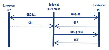 |
| Discovery and Registration Process |
After the endpoint discovers the location of the gatekeeper, it tries to register itself (RRQ). Such a registration includes (among other information):
- The addresses of the endpoint: for a terminal, this may be the user ids or telephone numbers. An endpoint may have more than one address. In theory it is possible that addresses belong to different users to enable multiple users to share a single phone - in practice, this depends on the phones and the gatekeeper implementation;
- Prefixes: if the registering endpoint is a gateway it may register number prefixes instead of addresses;
- Time to live: An endpoint may request how long the registration will last.This value can be overwritten by gatekeeper policies.
The gatekeeper checks the requested registration information and confirms the (possibly modified) values (RCF). It may also reject a registration request because of, for example, invalid addresses. In the case of a confirmation, the gatekeeper assigns a unique identifier to the endpoint, which will be used in subsequent requests to indicate that the endpoint is still registered.
Signalling models
Call signalling messages and H.245 control messages may be exchanged either end-to-end between calling party and called party or through a gatekeeper. Depending on the role the gatekeeper plays in the call signalling and in the H.245 signalling, the H.323 specification foresees three different types of signalling models:
- Direct signalling: With this signalling model, only H.225.0 RAS messages are routed through the gatekeeper while the other logical channel messages are directly exchanged between the two endpoints;
- Gatekeeper-routed call signalling: With this signalling model, H.225.0 RAS and H.225.0 call signalling messages are routed through the gatekeeper, while the H.245 Conference Control messages are directly exchanged between the two endpoints;
- Gatekeeper-routed H.245 control, H.225.0 RAS and H.225.0: Call signalling and H.245 Conference Control messages are routed through the gatekeeper and only the media streams are directly exchanged between the two endpoints.
Communication phases
In a H.323, communication may be identified in five different phases:
- Call set up;
- Initial communication and capability exchange;
- Establishment of audio-visual communication;
- Call services;
- Call termination.
H.235 Security
The H.235 recommendation defines elements of security for H.323:
- Authentication: Authentication can be achieved by using a shared secret (password) or digital signatures. The RAS messages include a token that was generated using either the shared secret or the signature. A receiving entity authenticates the sender by comparing the received token with a self-generated token;
- Message Integrity: Integrity is achieved by generating password-based checks on the message;
Privacy Mechanisms are provided to setup encryption on the media streams. They must be used in conjunction with the H.245 protocol and employ DES, Triple DES or RC2.The use of SRTP is not supported yet (in H.235v2).
Features of H.323
- H.323 call routing with Cisco CallManager: With H.323, Cisco CallManager only sees the router as one gateway. Calls are sent to the gateway but Cisco CallManager cannot specify which port the call is sent to. Cisco CallManager does not even know that multiple ports exist on the gateway.
In the reverse direction, an H.323 gateway can decide where to send individual calls. Some calls can go to Cisco CallManager and other calls can go directly to other H.323 gateways without involving Cisco CallManager.
- H.323 gatekeeper: A gatekeeper is an H.323 entity on the network that provides services such as address translation and network access control for H.323 terminals, gateways, and multipoint control units (MCUs). Gatekeepers also provide other services such as bandwidth management, accounting, and dial plans that you can centralize in order to provide scalability.
Gatekeepers are logically separated from H.323 endpoints such as terminals and gateways. They are optional in an H.323 network. But if a gatekeeper is present, endpoints must use the services provided. Refer to Understanding H.323 Gatekeepers for more information.
- Cisco IOS H.323 gateway with Cisco CallManager: Refer to Cisco IOS H.323 Gateway Configuration for Use with Cisco CallManager for the configuration details of a Cisco IOS H.323 gateway with Cisco CallManager.
- H.323 gateway dial-peer configuration for Cisco CallManager server redundancy: Cisco IOS H.323 gateways can be configured for Cisco CallManager server redundancy so that if the primary Cisco CallManager server fails, the secondary Cisco CallManager server takes over and the IP phones re-home to the secondary server. Refer to H.323 Gateway Dial-Peer Configuration for Cisco CallManager Server Redundancy for more information.
- Caller ID: H.323 provides caller ID from Foreign Exchange Office (FXO) and T1 channel associated signaling (CAS) ports
- Fractional PRI support: H.323 supports the use of Fractional PRI.
- Interoperability: H.323 is widely used and interoperates well with applications and devices from multiple vendors.
- Non-Facility Associated Signaling (NFAS) support: Support for NFAS allows the H.323 Gateway to control more ISDN PRI lines with one D channel.
- Integrated access: Data and Voice on same T1/E1.
- Legacy systems support: More TDM interface types and signaling supported (for example, Analog-DID, E&M, T1 FGD, E1 R2…)
Applications and services
The vision of H.323 is interoperability between packet and circuit switched networks. H.323 also promises new value added services to the customers using circuit switched networks. These goals have not yet been achieved. Lower operational costs alone are not a reason good enough to switch to a new technology. Several Internet telephony service providers ITSPs have met the expectations of good services in North America and Europe, but the global interoperability is still a big problem. Furthermore the features and quality of service are often inferior to plain old telephone services POTS. The main reasons for not meeting the quality goals are the poor interoperability of the endpoints, especially gateways, of various vendors and the limited scalability of H.323 communications.
Advantages and Disadvantages of H.323 Protocol
Advantages
|
Disadvantages
|
Standard protocol
|
Peer-to-peer architecture lead to complex configuration requirement on each device
|
Supported by many VOIP vendors
|
Binary encoding of signaling messages which is tough to troubleshoot
|
Stable and mature
|
H.323 represents a suite of protocols for (voice, video and data) so it requires more processing power in terms of processor and memory
|
Support for modern VOIP features
|
-
|
----


Free Online Skill Test, e Tutorial, Video Tutorial & Training on CCNA,CCNP & CCIE
ReplyDeleteVisit- hub4Tech.com