
 |
| PSTN Network Architecture |
PSTN is the aggregate of the
world's circuit-switched telephone networks that are operated by national,
regional, or local telephony operators, providing infrastructure and services
for public telecommunication. The PSTN consists of telephone lines, fiber optic
cables, microwave transmission links, cellular networks, communications
satellites, and undersea telephone cables, all interconnected by switching
centers, thus allowing most telephones to communicate with each other.
Originally a network of fixed-line analog telephone systems, the PSTN is now
almost entirely digital in its core network and includes mobile and other
networks, as well as fixed telephones.
Plain
Old Telephone Service, which refers to the standard telephone service that
most homes use. In contrast, telephone services based on high-speed, digital
communications lines, such as ISDN and FDDI, are not POTS. The main
distinctions between POTS and non-POTS services are speed and bandwidth. POTS
is generally restricted to about 52 Kbps (52,000 bitsper second).
The technical operation of the
PSTN adheres to the standards created by the ITU-T. These standards allow
different networks in different countries to interconnect seamlessly. The E.163
and E.164 standards provide a single global address space for telephone
numbers. The combination of the interconnected networks and the single
numbering plan allow telephones around the world to dial each other.
1. History
The first telephones had no network but were in private use, wired together in pairs. Users who wanted to talk to different people had as many telephones as necessary for the purpose. A user who wished to speak whistled loudly into the transmitter until the other party heard.
However, a bell was added soon
for signaling, so an attendant no longer need wait for the whistle, and then a
switch hook. Later telephones took advantage of the exchange principle already
employed in telegraph networks. Each telephone was wired to a local telephone
exchange, and the exchanges were wired together with trunks. Networks were
connected in a hierarchical manner until they spanned cities, countries,
continents and oceans. This was the beginning of the PSTN, though the term was
not used for many decades.
Automation introduced pulse
dialing between the phone and the exchange, and then among exchanges, followed
by more sophisticated address signaling including multi-frequency, culminating
in the SS7 network that connected most exchanges by the end of the 20th
century.
The growth of the PSTN meant
that teletraffic engineering techniques needed to be deployed to deliver
quality of service (QoS) guarantees for the users. The work of A. K. Erlang
established the mathematical foundations of methods required to determine the
capacity requirements and configuration of equipment and the number of
personnel required to deliver a specific level of service.
In the 1970s the
telecommunications industry began implementing packet switched network data
services using the X.25 protocol transported over much of the end-to-end
equipment as was already in use in the PSTN.
In the 1980s the industry
began planning for digital services assuming they would follow much the same
pattern as voice services, and conceived a vision of end-to-end circuit
switched services, known as the Broadband Integrated Services Digital Network
(B-ISDN). The B-ISDN vision has been overtaken by the disruptive technology of
the Internet.
Beginning in the 1960s, voice
calls began to be digitized and manual switching was replaced by automated
electronic switching. Digital voice signals can share the same wire with many
other phone calls. The advent of fiber-optic cables now allows thousands of
calls to share the same line. But fiber-optic and other high-bandwidth cables
haven't changed the basic nature of circuit switching, which still requires a
connection -- or circuit -- to remain open for the length of the phone call.
At the turn of the 21st
century, the oldest parts of the telephone network still use analog technology
for the last mile loop to the end user. Digital services have been increasingly
rolled out to end users using services such as DSL, ISDN, FTTx, cable modem,
and online fax systems.
Several large private
telephone networks are not linked to the PSTN, usually for military purposes.
There are also private networks run by large companies which are linked to the
PSTN only through limited gateways, such as a large private branch exchange
(PBX).
2. Operators
The task of building the networks and selling services to customers fell to the network operators. The first company to be incorporated to provide PSTN services was the Bell Telephone Company in the United States.
Routing calls requires
multiple switching offices. The phone number itself is a coded map for routing
the call. In the India, for example, we have 10-digit phone numbers.
The first three digits are the
area code or national destination code (NDC), which helps route the call to the
right regional switching station.
The next three digits are the
exchange, which represents the smallest amount of circuits that can be bundled
on the same switch. In other words, when you make a call to another user in
your same exchange -- maybe a neighbor around the corner -- the call doesn't
have to be routed onto another switch.
The last four digits of the
phone number represent the subscriber number, which is tied to your specific
address and phone lines.
Within a company or larger
organization, each employee or department might have its own extension.
Extensions from the main phone number are routed through something called a
private branch exchange (PBX) that operates on the premises.
To make an international call
requires further instructions. The call needs to be routed through your
long-distance phone carrier to another country's long-distance phone carrier.
To signal such a switch, you have to dial two separate numbers, your country's
exit code (or international access code) and the corresponding country code of
the place you're calling.
3. Working
This chapter provides a fundamental view of how the PSTN works, particularly in the areas of signaling and digital switching. SS7 provides control signaling for the PSTN, so you should understand the PSTN infrastructure to fully appreciate how it affects signaling and switching.
- Network Topology
- PSTN Hierarchy
- Access and Transmission Facilities
- Network Timing
- The Central Office
- Integration of SS7 into the PSTN
- Evolving the PSTN to the Next Generation
4. Network
Topology
The topology of a network describes the various network nodes and how they interconnect. Regulatory policies play a major role in exactly how voice network topologies are defined in each country, but general similarities exist. While topologies in competitive markets represent an interconnection of networks owned by different service providers, monopolistic markets are generally an interconnection of switches owned by the same operator.
Depending on geographical
region, PSTN nodes are sometimes referred to by different names. The three node
types we discuss in this chapter include:
- End Office (EO): Also called a Local Exchange. The End Office provides network access for the subscriber. It is located at the bottom of the network hierarchy.
- Tandem: Connects EOs together, providing an aggregation point for traffic between them. In some cases, the Tandem node provides the EO access to the next hierarchical level of the network.
- Transit: Provides an interface to another hierarchical network level. Transit switches are generally used to aggregate traffic that is carried across long geographical distances.
There are two primary methods
of connecting switching nodes. The first approach is a mesh topology, in which
all nodes are interconnected. This approach does not scale well when you must
connect a large number of nodes. You must connect each new node to every
existing node. This approach does have its merits, however; it simplifies
routing traffic between nodes and avoids bottlenecks by involving only those
switches that are in direct communication with each other. The second approach
is a hierarchical tree in which nodes are aggregated as the hierarchy traverses from the
subscriber access points to the top of the tree. PSTN networks use a
combination of these two methods, which are largely driven by cost and the
traffic patterns between exchanges.
 |
| Generic PSTN Hierarchies |
5. PSTN Hierarchy
 |
| Original Telecommunications Hierarchy |
While Class 2 and Class 3
offices are seldom used in today's system, the original numbering system has
survived. Therefore, each top-level Class 1 office usually connects to multiple
Class 4 offices, skipping the old Classes 2 and 3. Each Class 4 office, in
turn, connects to multiple Class 5 offices. The Class 5 offices, or end offices, connect to individual
subscribers, as shown on the Current Telecommunications Hierarchy Diagram.
5.1. Class 5 Central Office: The Local Exchange |

The Class 5 CO is also called the end office or local office. It is the local workhorse for the telephone and data communications traffic in one local exchange. When you pick up your telephone at home, you receive dial tone from a Class 5 CO. There are currently about 1,500 Class 5 local exchanges in the United States.
The Class 5 office is the only
office that connects to individual or business subscribers. Offices higher in
this hierarchy have only lower level COs as their subscribers. However, each
Class 5 CO also connects to other nearby Class 5 offices, as well as its
"parent" Class 4 office one level up in the hierarchy.
If a subscriber places a call
to another subscriber connected to the same Class 5 office, that office makes
the connection directly, as shown on the Call within the Same Exchange Diagram.
 |
| Call Within the Same Exchange |
If the caller's Class 5 CO is
directly connected to the destination Class 5 CO, the calling CO passes the
call directly to the destination CO, which completes the call to the
destination subscriber, as shown on the Calling Handoff Diagram.
 |
| Calling Handoff |
 |
| Tandem Switching |
6. Access and Transmission Facilities
 |
| End Office Facility Interfaces |
6.1. Lines
Lines are used to connect the
subscriber to the CO, providing the subscriber access into the PSTN. The
following sections describe the facilities used for lines, and the access
signaling between the subscriber and the CO.
- The Local Loop
- Analog Line Signaling
- Dialing
- Ringing and Answer
- Voice Encoding
- ISDN BRI
6.1.1. The Local
Loop
The local loop consists of a
pair of copper wires extending from the CO to a residence or business that
connects to the phone, fax, modem, or other telephony device. The wire pair
consists of a tip wire and a ring wire. The terms tip and ring are vestiges of
the manual switchboards that were used a number of years ago; they refer to the
tip and ring of the actual switchboard plug operators used to connect calls.
The local loop allows a subscriber to access the PSTN through its connection to
the CO. The local loop terminates on the Main Distribution Frame (MDF) at the
CO, or on a remote line concentrator.
Remote line concentrators,
also referred to as Subscriber Line Multiplexers or Subscriber Line
Concentrators, extend the line interface from the CO toward the subscribers,
thereby reducing the amount of wire pairs back to the CO and converting the
signal from analog to digital closer to the subscriber access point. In some
cases, remote switching centers are used instead of remote concentrators.
Remote switching centers
provide local switching between subtending lines without using the resources of
the CO. Remotes, as they are often generically referred to, are typically used
for subscribers who are located far away from the CO. While terminating the
physical loop, remotes transport the digitized voice stream back to the CO over
a trunk circuit, in digital form.
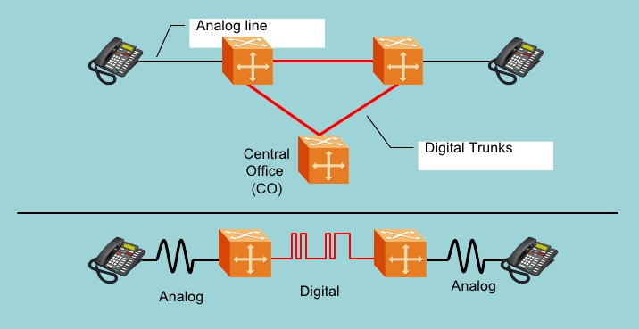
6.1.2. Analog Line
Signaling
Currently, most phone lines
are analog phone lines. They are referred to as analog lines because they use
an analog signal over the local loop, between the phone and the CO. The analog
signal carries two components that comprise the communication between the phone
and the CO: the voice component, and the signaling component.
The signaling that takes place
between the analog phone and the CO is called in-band signaling. In-band
signaling is primitive when compared to the out-of-band signaling used in
access methods such as ISDN; see the "ISDN BRI" section in this
chapter for more information. DC current from the CO powers the local loop between the phone and
the CO. The voltage levels vary between different countries, but an on-hook
voltage of –48 to –54 volts is common in North America and a number of other
geographic regions, including the United Kingdom.
6.1.3. Dialing
When a subscriber dials a
number, the number is signaled to the CO as either a series of pulses based on
the number dialed, or by Dual Tone Multi-Frequency (DTMF) signals. The DTMF
signal is a combination of two tones that are generated at different
frequencies. A total of seven frequencies are combined to provide unique DTMF
signals for the 12 keys (three columns by four rows) on the standard phone
keypad. Usually, the dialing plan of the CO determines when all digits have
been collected.
6.1.4. Ringing and
Answer
To notify the called party of
an incoming call, the CO sends AC ringing voltage over the local loop to the
terminating line. The incoming voltage activates the ringing circuit within the
phone to generate an audible ring signal. The CO also sends an audible
ring-back tone over the originating local loop to indicate that the call is
proceeding and the destination phone is ringing. When the destination phone is
taken off-hook, the CO detects the change in loop current and stops generating
the ringing voltage. This procedure is commonly referred to as ring trip. The
off-hook signals the CO that the call has been answered; the conversation path
is then completed between the two parties and other actions, such as billing,
can be initiated, if necessary.
6.1.5. Voice
Encoding
An analog voice signal must be
encoded into digital information for transmission over the digital switching
network. The conversion is completed using a codec (coder/decoder), which
converts between analog and digital data. The ITU G.711 standard specifies the
Pulse Coded Modulation (PCM) method used throughout most of the PSTN. An
analog-to-digital converter samples the analog voice 8000 times per second and
then assigns a quantization value based on 256 decision levels. The
quantization value is then encoded into a binary number to represent the
individual data point of the sample. Figure illustrates the process of sampling
and encoding the analog voice data.
 |
| Voice Encoding Process |
Two variations of encoding
schemes are used for the actual quantization values: A-law and m-Law encoding.
North America uses m-Law encoding, and European countries use A-law encoding.
When voice is transmitted from the digital switch over the analog loop, the
digital voice data is decoded and converted back into an analog signal before
transmitting over the loop.
The emergence of voice over IP
(VoIP) has prompted the use of other voice-encoding standards, such as ITU
G.723, G.726, and ITU G.729. These encoding methods use algorithms that produce
more efficient and compressed data, making them more suitable for use in packet
networks. Each encoding method involves trade-offs between bandwidth,
processing power required for the encoding/decoding function, and voice
quality. For example, G.711 encoding/decoding requires little processing and
produces high quality speech, but consumes more bandwidth. In contrast, G.723.1
consumes little bandwidth, but requires more processing power and results in
lower quality speech.
6.1.6.
ISDN BRI
Although Integrated Services
Digital Network (ISDN) deployment began in the 1980s, it has been a relatively
slow-moving technology in terms of number of installations. ISDN moves the
point of digital encoding to the customer premises. Combining ISDN on the
access portion of the network with digital trunks on the core network provides
total end-to-end digital connectivity. ISDN also provides out-of-band signaling
over the local loop. ISDN access signaling coupled with SS7 signaling in the
core network achieves end-to-end out-of-band signaling. ISDN access signaling
is designed to complement SS7 signaling in the core network.
There are two ISDN interface
types: Basic Rate Interface (BRI) for lines, and Primary Rate Interface (PRI)
for trunks. BRI multiplexes two bearer (2B) channels and one signaling (D)
channel over the local loop between the subscriber and the CO; this is commonly
referred to as 2B+D. The two B channels each operate at 64 kb/s and can be used
for voice or data communication. The D channel operates at 16 kb/s and is used
for call control signaling for the two B channels. The D channel can also be
used for very low speed data transmission. Within the context of ISDN reference
points, the local loop is referred to as the U-loop. It uses different
electrical characteristics than those of an analog loop.
Voice quantization is performed
within the ISDN phone (or a Terminal Adapter, if an analog phone is used) and
sent to a local bus: the S/T bus. The S/T bus is a four-wire bus that connects
local ISDN devices at the customer premises to a Network Termination 1 (NT1)
device. The NT1 provides the interface between the Customer Premises Equipment
(CPE) and the U-loop.
6.2. Trunks
Trunks carry traffic between
telephony switching nodes. While analog trunks still exist, most trunks in use
today are digital trunks, which are the focus of this section. Digital trunks
may be either four-wire (twisted pairs) or fiber optic medium for higher capacity. T1 and E1 are the
most common trunk types for connecting to End Offices. North American networks
use T1, and European networks use E1.
On the T1/E1 facility, voice
channels are multiplexed into digital bit streams using Time Division
Multiplexing (TDM). TDM allocates one timeslot from each digital data stream's
frame to transmit a voice sample from a conversation. Each frame carries a
total of 24 multiplexed voice channels for T1 and 30 channels for E1. The T1
frame uses a single bit for framing, while E1 uses a byte. Figure shows the
formats for T1 and E1 framing.
 |
| T1/E1 Framing Formats |
The E1 format also contains a
channel dedicated to signaling when using in-band signaling. The T1 format uses
"robbed bit" signaling when using in-band signaling. The term
"robbed bit" comes from the fact that bits are taken from the PCM
data to convey trunk supervisory signals, such as on/off-hook status and winks.
This is also referred to as A/B bit signaling. In every sixth frame, the least
significant bits from each PCM sample are used as signaling bits. In the case
of Extended Superframe trunks (ESF), A/B/C/D bits are used to indicate trunk
supervision signals. A/B bit signaling has been widely replaced by SS7
signaling, but it still exists in some areas.
Trunks are multiplexed onto
higher capacity transport facilities as traffic is aggregated toward tandems
and transit switches. The higher up in the switching hierarchy, the more likely
optical fiber will be used for trunk facilities for its increased bandwidth
capacity. In North America, Synchronous Optical Network (SONET) is the standard
specification for transmission over optical fiber. SONET defines the physical
interface, frame format, optical line rates, and an OAM&P protocol. In
countries outside of North America, Synchronous Digital Hierarchy (SDH) is the
equivalent optical standard. Fiber can accommodate a much higher bandwidth than
copper transmission facilities, making it the medium of choice for high-density
trunking.
Standard designations describe
trunk bandwidth in terms of its capacity in bits/second. The basic unit of
transmission is Digital Signal 0 (DS0), representing a single 64 kb/s channel
that occupies one timeslot of a Time Division Multiplex (TDM) trunk.
Transmission rates are calculated in multiples of DS0 rates. For example, a T1 uses 24 voice channels at 64 kb/s per channel to produce a DS1
transmission rate of 1.544 mb/s, calculated as follows:
24 x 64 kb/s = 1.536 kb/s +
8000 b/s framing bits = 1.544 mb/s
The optical transmission rates
in the SONET transport hierarchy are designated in Optical Carrier (OC) units.
OC-1 is equivalent to T3. Higher OC units are multiples of OC-1; for example,
OC-3 is simply three times the rate of OC-1. In North America, the electrical
equivalent signals are designated as Synchronous Transport Signal (STS) levels.
The ITU SDH standard uses the STM to designate the hierarchical level of
transmission. Table_1 summarizes the electrical transmission rates, and Table_2
summarizes the SONET/SDH transmission rates.
Table_1: Electrical
Transmission Rates
Designation
|
Voice Channels
|
Transmission Rate Mb/s
|
T1 (North America)
|
24
|
1.544
|
E1 (Europe)
|
30
|
2.048
|
E3 (Europe)
|
480
|
34.368
|
T3 (North America)
|
672
|
44.736
|
Table_2: SONET/SDH
Transmission Rates
SONET Optical Level
|
SONET Electrical Level
|
SDH Level
|
Voice Channels
|
Transmission Rate Mb/s
|
OC-1
|
STS-1
|
—
|
672
|
51.840
|
OC-3
|
STS-3
|
STM-1
|
2016
|
155.520
|
OC-12
|
STS-12
|
STM-4
|
8064
|
622.080
|
OC-48
|
STS-48
|
STM-16
|
32,256
|
2488.320
|
OC-96
|
STS-96
|
STM-32
|
64,512
|
4976.64
|
OC-192
|
STS-192
|
STM-64
|
129,024
|
9953.280
|
OC-768
|
STS-768
|
STM-256
|
516,096
|
39,813.120
|
6.3. ISDN PRI
Primary Rate Interface (PRI)
provides ISDN access signaling over trunks and is primarily used to connect
PBXs to the CO. As with BRI, PRI converts all data at the customer premises
into digital format before transmitting it over the PRI interface. In the
United States, PRI uses 23 bearer channels for voice/data and one signaling
channel for call control. The single signaling channel handles the signaling
for calls on the other 23 channels. This scheme is commonly referred to as
23B+D. Each channel operates at a rate of 64 kb/s. Figure 5-8 illustrates a PBX
connected to the CO through a PRI trunk.
 |
| ISDN Primary Rate Interface |
In Europe, PRI is based on 32
channels at a transmission rate of 2.048 Mb/s. There are 30 bearer channels and
two signaling channels, which are referred to as 30B+2D.
7. Network
Timing
Digital trunks between two connecting nodes require clock synchronization in order to ensure proper framing of the voice channels. The sending switch clocks the bits in each frame onto the transmission facility. They are clocked into the receiving switch at the other end of the facility. Digital facility interfaces use buffering techniques to store the incoming frame and accommodate slight variation in the timing of the data sent between the two ends. A problem arises if the other digital switch that is connected to the facility has a clock signal that is out of phase with the first switch. The variation in clock signals eventually causes errors in identifying the beginning of a frame. This condition is known as slip, and it results in buffer overrun or buffer underrun. Buffer overrun occurs if the frequency of the sending clock is greater than the frequency of the receiving clock, discarding an entire frame of data. Buffer underrun occurs if the frequency of the sending clock is less than the frequency of the receiving clock, repeating a frame of data. Occasional slips do not present a real problem for voice calls, although excessive slips result in degraded speech quality. However, they are more detrimental to the data transfer, in which each bit is important. Therefore, synchronization of time sources between the digital switches is important. Because digital transmission facilities connect switches throughout the network, this requirement escalates to a network level, where the synchronization of many switches is required.
There are various methods of
synchronizing nodes. One method involves a single master clock source, from
which other nodes derive timing in a master/slave arrangement. Another method
uses a plesiochronous arrangement, where each node contains an independent
clock whose accuracy is so great that it remains independently synchronized
with other nodes. You can also use a combination of the two methods by using
highly accurate clocks as a Primary Reference Source (PRS) in a number of
nodes, providing timing to subtending nodes in the network.
The clocks' accuracy is rated
in terms of stratum levels. Stratums 1 through 4 denote timing sources in order
of descending accuracy. A stratum 1 clock provides the most accurate clock
source with a free-running accuracy of ±1 x 10 -11, meaning only one error can
occur in 1011 parts. A stratum 4 clock provides an accuracy of ±32 x 10-6.
Since the deployment of Global
Positioning System (GPS) satellites, each with a number of atomic clocks
on-board, GPS clocks have become the preferred method of establishing a clock
reference signal. Having a GPS clock receiver at each node that receives a
stratum 1-quality timing signal from the GPS satellite flattens the distributed
timing hierarchy. If the GPS receiver loses the satellite signal, the receiver
typically runs free at stratum 2 or less. By using a flattened hierarchy based
on GPS receivers, you remove the need to distribute the clock signal and
provide a highly accurate reference source for each node. Figure shows an
example that uses a stratum 1 clock at a digital switching office to distribute
timing to subtending nodes, and also shows an example that uses a GPS satellite
clock receiver at each office.
 |
| Network Timing for Digital Transmission |
8. Integration
of SS7 into the PSTN
This section provides a brief overview of how the SS7 architecture is applied to the PSTN. Since SS7 has not been presented in great detail, the examples and information are brief and discussed only in the context of the network nodes presented in this section.
The PSTN existed long before
SS7. The network's general structure was already in place, and it represented a
substantial investment. The performance requirement mandated by the 800
portability act of 1993 was one of the primary drivers for the initial
deployment of SS7 by ILECs in the United States. IXCs embraced SS7 early to cut
down on post-dial delay which translated into significant savings on
access/egress charges. Federal regulation, cost savings, and the opportunity to
provide new revenue generating services created a need to deploy SS7 into the
existing PSTN.
SS7 was designed to integrate
easily into the existing PSTN, to preserve the investment and provide minimal
disruption to the network. During SS7's initial deployment, additional hardware
was added and digital switches received software upgrades to add SS7 capability
to existing PSTN nodes. In the SS7 network, a digital switch with SS7
capabilities is referred to as a Service Switching Point (SSP). When looking at
the SS7 network topologies in later chapters, it is important to realize that
the SSP is not a new node in the network.
Instead, it describes an
existing switching node, to which SS7 capabilities have been added. Similarly,
SS7 did not introduce new facilities for signaling links, but used timeslots on
existing trunk facilities. PSTN diagrams containing End Offices and tandems
connected by trunks represent the same physical facilities as those of SS7
diagrams that show SSP nodes with interconnecting links. The introduction of
SS7 added new nodes, such as the STP and SCP; however, all of the switching
nodes and facilities that existed before SS7 was introduced are still in place. Figure shows a simple
view of the PSTN, overlaid with SS7-associated signaling capabilities.
 |
| SS7 Overlaid onto the PSTN |
8.1. SS7 Link Interface
The most common method for
deploying SS7 links is for each link to occupy a timeslot, such as a T1 or E1,
on a digital trunk. As shown in Figure 5-12, the signaling links actually
travel on the digital trunk transmission medium throughout the network. At each
node, the SS7 interface equipment must extract the link timeslot from the
digital trunk for processing. This process is typically performed using a
channel bank, or a Digital Access and Cross-Connect (DAC), which demultiplexes
the TDM timeslot from the digital trunk. The channel bank, or DAC, can extract
each of the timeslots from the digital stream, allowing them to be processed
individually. The individual SS7 link provides the SS7 messages to the digital
switch for processing. While implementations vary, dedicated peripheral
processors usually process the lower levels of the SS7 protocol (Level 1, Level
2, and possibly a portion of Level 3); call- and service-related information is
passed on to the central processor, or to other peripheral processors that are
designed for handling call processing–related messages. Of course, this process
varies based on the actual equipment vendor.
9. Evolving the
PSTN to the Next Generation
The expansion of the Internet continues to drive multiple changes in the PSTN environment. First, more network capacity is used to transport data over the PSTN. Dial-up Internet services use data connections that are set up over the PSTN to carry voice-band data over circuit-switched connections. This is a much different situation than sending data over a data network. Data networks use packet switching, in which many data transactions share the same facilities. Circuit-switched connections are dedicated connections, which occupy a circuit for the duration of a call. The phone networks were originally engineered for the three-minute call, which was the average length used for calculations when engineering the voice network. Of course, Internet connections tend to be much more lengthy, meaning that more network capacity is needed. The changes driven by the Internet, however, reach much further than simply an increase in network traffic. Phone traffic is being moved to both private packet-based networks and the public Internet, thereby providing an alternative to sending calls over the PSTN. Several different architectures and protocols are competing in the VoIP market to establish alternatives to the traditional circuit-switched network presented in this chapter. The technologies are not necessarily exclusive; some solutions combine the various technologies. Among the current leading VoIP technologies are:
- Soft switches
- H.323
- Session Initiation Protocol (SIP)
Each of these VoIP
architectures uses VoIP-PSTN gateways to provide some means of communication
between the traditional PSTN networks and VoIP networks. These gateways provide
access points for interconnecting the two networks, thereby creating a
migration path from PSTN-based phone service to VoIP phone service. The core
network interface connections for VoIP into the PSTN are the trunk facilities
that carry the voice channels and the signaling links that carry SS7 signaling.
PRI is also commonly used for business to network access. Figure shows the
interconnection of VoIP architectures to the PSTN using signaling gateways and
trunking gateways. Chapter 14, "SS7 in the Converged World,"
discusses these VoIP technologies in more detail.
 |
| VoIP Gateways to the PSTN |
10. VoIP Gateways to the PSTN
Dr. Harry Nyquist (and many others) created a process that allows equipment to convert Analog signals (flowing waveforms) into digital format (1s and 0s). After plenty of research, He found that he could accurately reconstruct audio streams by taking samples that numbered twice the highest audio frequency used in the audio. Here is how it breaks down. Audio frequencies vary based on the volume, pitch, and so on that comprises the sound. Here are a few key facts:
- The average human ear is able to hear frequencies from 20–20,000 Hz.
- Human speech uses frequencies from 200–9,000 Hz.
- Telephone channels typically transmit frequencies from 300–3,400 Hz.
- The Nyquist theorem is able to reproduce frequencies from 300–4,000 Hz
 |
| Analog Signal Sample |
- Sampling: It is the reduction of a continuous signal to a discrete signal. A sample refers to a value or set of values at a point in time and/or space.
- Quantization: After the digitizing device has taken thousands of samples of the Analog audio, it then matches each sample to a voltage scale. This process is known as quantization. It assigns a value from the voltage range based on the amplitude of each audio sample. The quantization process divides the voltage range into 16 total segments (0 to 7 positive and 0 to 7 negative).
- Encoding: In the first step of the digitization process, the Analog voice is sampled using PAM. The second step of the process then matches the PAM sample to a specific voltage value. In this step, the digitizing equipment converts the sample value into an 8-bit, binary number. This final conversion is known as pulse-code modulation (PCM).
- Compression (optional): Some voice systems allow you to save bandwidth by compressing the audio before sending it to the remote device. The compression methods vary in overhead and audio quality, but many of them can save a significant amount of bandwidth with little quality degradation.
11. Role of Digital
Signal Processors
Cisco designed its routers with one primary purpose in mind: routing. Moving packets between one location and another is not a processor-intensive task, thus Cisco routers are not equipped with the kind of memory and processing resources typical PCs are equipped with. For example, from a router’s perspective, having 256 MB of RAM is quite a bit. From a PC’s perspective, 256 MB will barely help you survive the Microsoft Windows boot process.
Moving into the realm of VoIP,
the network now requires the router to convert loads of voice into digitized,
packetized transmissions. This task would easily overwhelm the resources you
have on the router. This is where DSPs come into play. DSPs offload the
processing responsibility for voice-related tasks from the processor of the
router.
 |
| RAM used for Packet Processing |
12. Understanding RTP and RTCP
When you walk into the VoIP world, you encounter a whole new host of protocol standards. Think of the Real-time Transport Protocol (RTP) and Real-time Transport Control Protocol (RTCP) as the protocols of voice. RTP operates at the transport layer of the OSI model on top of UDP. Having two transport layer protocols is odd, but that’s exactly what is happening here. UDP provides the services it always does: port numbers (that is, session multiplexing) and header checksums (which ensure that the header information does not become corrupted). RTP adds time stamps and sequence numbers to the header information. This allows the remote device to put the packets back in order when it receives them at the remote end (function of the sequence number) and use a buffer to remove jitter (slight delays) between the packets to give a smooth audio playout (function of the time stamp). Figure represents the RTP header information contained in a packet.
 |
| Protocol Packet Header |
At the time the devices
establish the call, RTCP also engages. Although this protocol sounds important,
its primary job is statistics reporting. It delivers statistics between the two
devices participating in the call, which include:
- Packet count
- Packet delay
- Packet loss
- Jitter (delay variations)
Although this information is
useful, it is not nearly as critical as the actual RTP audio streams. Keep this
in mind when you configure QoS settings. AS the devices establish the call, the
RTP audio streams use an even UDP port from 16,384 to 32,767, as previously
discussed. RTCP creates a separate session over UDP between the two devices by
using an odd-numbered port from the same range. Throughout the call duration,
the devices send RTCP packets at least once every 5 seconds. The Cisco Unified
Communication Manager Express (CME) router can log and report this information,
which allows you to determine the issues that are causing call problems (such
as poor audio, call disconnects, and so on) on the network.
13. Comparison between Circuit-Switched & Packet-Switched
Item
|
Circuit-Switched
|
Packet-Switched
|
Call Setup
|
Required
|
Not Needed
|
Dedicated Physical Path
|
Yes
|
No
|
Each packet follows the same route
|
Yes
|
No
|
Packets arrive in order
|
Yes
|
No
|
Is a switch crash fatal
|
Yes
|
No
|
Bandwidth available
|
Fixed
|
Dynamic
|
When can congestion occur
|
At setup Time
|
On every packet
|
Potentially wasted bandwidth
|
Yes
|
No
|
Store-and-forward transmission
|
No
|
Yes
|
Transparency
|
Yes
|
No
|
Charging
|
Per Min.
|
Per Packet
|
14. Connection Mode & Connection Summarized
Transfer Modes
|
Protocols
|
Connection Types
|
Protocols
|
Circuit Switching
·
Developed for voice
·
Nowadays also for data
·
Well-specified delays
·
Echo problems
|
·
PSTN
·
ISDN
·
PCM
|
Connection Oriented
·
Hand-shaking
·
strict error requirements
·
for fast data transfer
|
·
ATM
·
Frame-Relay
·
x.25
|
Packet Switching
·
Developed for data
·
Nowadays also for voice
·
Statistical multiplexing
·
Variable delays
|
·
IP
·
Frame-Relay
·
ATM
|
Connectionless
·
Broadcasting
·
Modest error rates often accepted
·
Fast data in good channels
|
·
IP
·
UDP
|
----


No comments:
Post a Comment