
Frame Relay is a high-performance WAN protocol that operates
at the physical and data link layers of the OSI reference model. Frame Relay
originally was designed for use across Integrated Services Digital Network
(ISDN) interfaces. Today, it is used over a variety of other network interfaces
as well.
Frame relay is a type of WAN connection use to connect one
site to many remote sites through a single physical circuit; this operation
makes it easy to construct reliable and inexpensive networks.
 |
| Frame Relay |
Frame Relay network is very simple. Frame Relay connections
are created by configuring network routers or other devices to communicate with
a service provider Frame Relay switch. The service provider configures the
Frame Relay switch, which helps keep end-user configuration tasks to a minimum.
Frame Relay has lower overhead than X.25 because it has fewer
capabilities e.g, Frame Relay does not provide error correction; modern WAN
facilities offer more reliable connection services and a higher degree of
reliability than older facilities. The Frame Relay node simply drops packets
without notification when it detects errors. Any necessary error correction,
such as re-transmission of data, is left to the endpoints. This makes
propagation from customer end to customer end through the network very fast.
Frame Relay network uses permanent virtual circuits (PVCs).
PVC is the logical path along an originating Frame Relay link, through the
network, and along a terminating Frame Relay link to its ultimate destination.
Compare this to the physical path used by a dedicated connection. In a network
with Frame Relay access, PVC uniquely defines the path between two endpoints.
Each virtual circuit is identified by a Data Link Connection
Identifier (DLCI), which is simply a number between 0 and 1023. In fact, Cisco
routers can only use DLCI numbers in the range 16 through 1007 to carry user
data.
Frame Relay is an example of a packet-switched technology.
Packet-switched networks enable end stations to dynamically share the network
medium and the available bandwidth.
The following two techniques are used in Packet-Switching Technology:
- Variable-Length Packets are used for more efficient and flexible data transfers. These packets are switched between the various segments in the network until the destination is reached.
- Statistical Multiplexing techniques control network access in a packet-switched network. The advantage of this technique is that it accommodates more flexibility and more efficient use of bandwidth. Most of today's popular LANs, such as Ethernet and Token Ring, are packet-switched networks.
Frame Relay Standardization
Initial proposals for the standardization of Frame Relay were
presented to the Consultative Committee on International Telephone and
Telegraph (CCITT) in 1984. Because of lack of interoperability and lack of
complete standardization, however, Frame Relay did not experience significant
deployment during the late 1980s.
A major development in Frame Relay's history occurred in 1990
when Cisco, Digital Equipment Corporation (DEC), Northern Telecom, and
StrataCom formed a consortium to focus on Frame Relay technology development.
This consortium developed a specification that conformed to the basic Frame
Relay protocol that was being discussed in CCITT, but it extended the protocol
with features that provide additional capabilities for complex internetworking
environments. These Frame Relay extensions are referred to collectively as the
Local Management Interface (LMI).
Since the consortium's specification was developed and
published, many vendors have announced their support of this extended Frame
Relay definition. ANSI and CCITT have subsequently standardized their own
variations of the original LMI specification, and these standardized
specifications now are more commonly used than the original version.
Internationally, Frame Relay was standardized by the
International Telecommunication Union-Telecommunications Standards Section
(ITU-T). In the United States, Frame Relay is an American National Standards
Institute (ANSI) standard.
Frame Relay Devices
Devices attached to a Frame Relay WAN fall into the following
two general categories:
- Data terminal equipment (DTE)
- Data circuit-terminating equipment (DCE)
 |
| Relationship between the two categories of devices |
DTEs generally are considered to be terminating equipment for
a specific network and typically are located on the premises of a customer. In
fact, they may be owned by the customer. Examples of DTE devices are terminals,
personal computers, routers, and bridges.
DCEs are carrier-owned internetworking devices. The purpose
of DCE equipment is to provide clocking and switching services in a network,
which are the devices that actually transmit data through the WAN. In most
cases, these are packet switches.
Frame Relay Structure
Standards for the Frame Relay protocol have been developed by
ANSI and CCITT simultaneously. The separate LMI specification has basically
been incorporated into the ANSI specification. The following discussion of the
protocol structure includes the major points from these specifications.
The Frame Relay frame structure is based on the LAPD
protocol. In the Frame Relay structure, the frame header is altered slightly to
contain the Data Link Connection Identifier (DLCI) and congestion bits, in
place of the normal address and control fields.
 |
| Frame Relay Header |
This new Frame Relay header is 2 bytes in length and has the
following format:
1. DLCI- 10-bit DLCI field represents the address of the frame and
corresponds to a PVC.
2. C/R- Designates whether the frame is a command or response.
3. EA- Extended Address field signifies up to two additional bytes
in the Frame Relay header, thus greatly expanding the number of possible
addresses.
4. FECN- Forward Explicit Congestion Notification (see ECN below).
5. BECN- Backward Explicit Congestion Notification (see ECN below).
6. DE (Discard Eligibility)- When there is congestion on the line, the network must decide
which frames to discard in order to free the line. Discard Eligibility provides
the network with a signal to determine which frames to discard. The network
will discard frames with a DE value of 1 before discarding other frames.
The DE bit may be set by the user on some of its
lower-priority frames. Alternatively, the network may set the DE bit to
indicate to other nodes that a frame should be preferentially selected for
discard, if necessary.
7. Information- The Information field may include other protocols within it,
such as an X.25, IP or SDLC (SNA) packet.
Frame Relay Virtual Circuits
Frame Relay provides connection-oriented data link layer
communication. This means that a defined communication exists between each pair
of devices and that these connections are associated with a connection
identifier. This service is implemented by using a Frame Relay virtual circuit,
which is a logical connection created between two data terminal equipment (DTE)
devices across a Frame Relay packet-switched network (PSN).
Virtual circuits provide a bidirectional communication path
from one DTE device to another and are uniquely identified by a data-link
connection identifier (DLCI). A number of virtual circuits can be multiplexed
into a single physical circuit for transmission across the network. This
capability often can reduce the equipment and network complexity required to
connect multiple DTE devices.
A virtual circuit can pass through any number of intermediate
DCE devices (switches) located within the Frame Relay PSN.
Frame Relay virtual circuits fall into two categories:
- Switched Virtual Circuits
Switched virtual circuits (SVCs) are temporary connections
used in situations requiring only sporadic data transfer between DTE devices
across the Frame Relay network.
A communication session across an SVC consists
of the following four operational states:
1. Call setup- The virtual circuit between two Frame Relay DTE
devices is established.
2. Data Transfer- Data is transmitted between the DTE devices
over the virtual circuit.
3. Idle- The connection between DTE devices is still active,
but no data is transferred. If an SVC remains in an idle state for a defined
period of time, the call can be terminated.
4. Call termination- The virtual circuit between DTE devices is
terminated.
After the virtual circuit is terminated, the DTE devices must
establish a new SVC if there is additional data to be exchanged. It is expected
that SVCs will be established, maintained, and terminated using the same
signaling protocols used in ISDN.
- Permanent Virtual Circuits
Permanent virtual circuits (PVCs) are permanently established
connections that are used for frequent and consistent data transfers between
DTE devices across the Frame Relay network. Communication across a PVC does not
require the call setup and termination states that are used with SVCs.
PVCs
always operate in one of the following two operational states:
1. Data transfer- Data is transmitted between the DTE devices
over the virtual circuit.
2. Idle- The connection between DTE devices is active, but no
data is transferred. Unlike SVCs, PVCs will not be terminated under any
circumstances when in an idle state.
DTE devices can begin transferring data whenever they are
ready because the circuit is permanently established.
Data-Link Connection Identifier
Frame Relay virtual circuits are identified by data-link
connection identifiers (DLCIs). DLCI values typically are assigned by the Frame
Relay service provider (for example, the telephone company).
 |
| A Single Frame Relay Virtual Circuit Can Be Assigned Different DLCIs on Each End of a VC |
Frame Relay DLCIs have local significance, which means that
their values are unique in the LAN, but not necessarily in the Frame Relay WAN.
Frame Relay Network Implementation
A common private Frame Relay network implementation is to
equip a T1 multiplexer with both Frame Relay and non-Frame Relay interfaces.
Frame Relay traffic is forwarded out the Frame Relay interface and onto the
data network. Non-Frame Relay traffic is forwarded to the appropriate
application or service, such as a private branch exchange (PBX) for telephone
service or to a video-teleconferencing application.
A typical Frame Relay network consists of a number of DTE
devices, such as routers, connected to remote ports on multiplexer equipment
via traditional point-to-point services such as T1, fractional T1, or 56-Kb
circuits.
The majority of Frame Relay networks deployed today are
provisioned by service providers that intend to offer transmission services to
customers. This is often referred to as a public Frame Relay service. Frame
Relay is implemented in both public carrier-provided networks and in private
enterprise networks. The following section examines the two methodologies for
deploying Frame Relay.
- Public Carrier-Provided Networks
In public carrier-provided Frame Relay networks, the Frame
Relay switching equipment is located in the central offices of a
telecommunications carrier. Subscribers are charged based on their network use
but are relieved from administering and maintaining the Frame Relay network
equipment and service.
Generally, the DCE equipment also is owned by the telecommunications
provider. DTE equipment either will be customer-owned or perhaps will be owned
by the telecommunications provider as a service to the customer.
The majority of today's Frame Relay networks are public
carrier-provided networks.
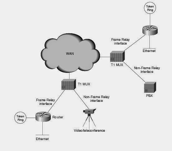 |
| A Simple Frame Relay Network Connects Various Devices to Different Services over a WAN |
- Private Enterprise Networks
More frequently, organizations worldwide are deploying
private Frame Relay networks. In private Frame Relay networks, the
administration and maintenance of the network are the responsibilities of the
enterprise (a private company). All the equipment, including the switching
equipment, is owned by the customer.
Benefits of Frame Relay
- Cost Effectiveness
Frame Relay reduces network costs by using less equipment,
less complexity, and an easier implementation. Frame Relay is a more cost-effective
option for two reasons.
- First, with dedicated lines, customers pay for an end-to-end connection. That includes the local loop and the network link. With Frame Relay, customers only pay for the local loop, and for the bandwidth they purchase from the network provider. Distance between nodes is not important. While in a dedicated-line model, customers use dedicated lines provided in increments of 64 kb/s, Frame Relay customers can define their virtual circuit needs in far greater granularity, often in increments as small as 4 kb/s.
- Frame Relay' shares bandwidth across a larger base of customers. Typically, a network provider can service 40 or more 56 kb/s customers over one T1 circuit. Using dedicated lines would require more DSU/CSUs (one for each line) and more complicated routing and switching. Network providers save because there is less equipment to purchase and maintain.
- Frame Relay provides greater bandwidth, reliability, and resiliency than private or leased lines.
- Flexibility
Virtual circuit provides considerable flexibility in network
design. In Frame Relay, the end of each connection has a number to identify it
called a Data Link Connection Identifier (DLCI). Any station can connect with
any other simply by stating the address of that station and DLCI number of the
line it needs to use.
How to configure Frame Realy
Configuring Frame Relay involves the following steps:
Change the encapsulation
Go in interface mode and select the Frame Relay encapsulation
on the interface. There are two types of Frame Relay encapsulations: Cisco and
IETF. Cisco is the default. Syntax to set your encapsulation is
encapsulation frame-relay [ietf]
Configure LMI type
The three LMI types are Cisco, Ansi, and Q933a. For IOS 11.2
and higher, the LMI type is automatically detected
frame-relay lmi-type [cisco | ansi | 933a]
Configure Frame Relay map
configuring a static Frame Relay map, is optional unless you
are using subinterfaces. The Frame Relay map will map a Layer 3 address to a
local DLCI. This step is optional because inverse-arp will automatically
perform this map for you.
The syntax for a Frame Relay map is as follows:
frame-relay map protocol
address dlci [broadcast] [cisco | ietf]
Configure subinterfaces
If you are using a routing protocol in a hub-and-spoke
topology, you will probably want to use subinterfaces to avoid the
split-horizon problem. To configure a subinterface, remove the IP address off
the main interface and put it under the subinterface. Configuring a
subinterface involves assigning it a number and specifying the type. The
following command creates point-to-point subinterface serial0/0.1
Router(config)#interface serial0/0.1 point-to-point
To create a multipoint subinterface, enter multipoint
instead:
Router(config)#interface serial0/0.1 multipoint
Assign IP address to subinterface
After entering one of these commands you will be taken to the
subinterface configuration mode where you can enter your IP address:
Router(config-subif)#ip
address 10.0.0.2 255.0.0.0
If you are using a multipoint subinterface, you will need to
configure frame-relay maps and you cannot rely on inverse-arp.
If you are using a point-to-point subinterface, you will need
to assign a DLCI to the subinterface. This is only for point-to-point
subinterfaces; this is not needed on the main interface or on multipoint
subinterfaces. To assign a DLCI to a point-to-point subinterface, enter the
following command under the subinterface:
frame-relay interface-dlci dlci
Configuration of Frame Relay
 |
| Frame Relay Configuration Topology |
Now first configure R1. Fast Ethernet port and hostname is
already configured. Double click on R1 and configure serial port for frame
relay encapsulation and further create sub interface for connecting R2, R3, R4.
Configure also static route for connecting remaining network.
Configure R1
R1>enable
R1#configure terminal
R1(config)#interface serial
0/0/0
R1(config-if)#encapsulation
frame-relay
R1(config-if)#no shutdown
R1(config-if)#exit
R1(config-subif)#interface
serial 0/0/0.102 point-to-point
R1(config-subif)#ip address
192.168.1.245 255.255.255.252
R1(config-subif)#frame-relay
interface-dlci 102
R1(config-subif)#exit
R1(config)#interface serial
0/0/0.103 point-to-point
R1(config-subif)#ip address
192.168.1.249 255.255.255.252
R1(config-subif)#frame-relay
interface-dlci 103
R1(config-subif)#exit
R1(config)#interface serial
0/0/0.104 point-to-point
R1(config-subif)#ip address
192.168.1.253 255.255.255.252
R1(config-subif)#frame-relay
interface-dlci 104
R1(config-subif)#exit
R1(config)#ip route
192.168.1.64 255.255.255.224 192.168.1.246
R1(config)#ip route
192.168.1.96 255.255.255.224 192.168.1.250
R1(config)#ip route
192.168.1.128 255.255.255.224 192.168.1.254
R1(config)#exit
Configure R2
R2>enable
R2#configure terminal
R2(config)#interface serial
0/0/0
R2(config-if)#encapsulation
frame-relay
R2(config-if)#no shutdown
R2(config-if)#exit
R2(config)#interface serial
0/0/0.101 point-to-point
R2(config-subif)#ip address
192.168.1.246 255.255.255.252
R2(config-subif)#frame-relay
interface-dlci 101
R2(config-subif)#exit
R2(config)#ip route 0.0.0.0
0.0.0.0 192.168.1.245
Configure R3
R3>enable
R3#configure terminal
R3(config)#interface serial
0/0/0
R3(config-if)#encapsulation
frame-relay
R3(config-if)#no shutdown
R3(config-if)#exit
R3(config)#interface serial
0/0/0.101 point-to-point
R3(config-subif)#ip address
192.168.1.250 255.255.255.252
R3(config-subif)#frame-relay
interface-dlci 101
R3(config-subif)#exit
R3(config)#ip route 0.0.0.0
0.0.0.0 192.168.1.249
Configure R4
R4>enable
R4#configure terminal
R4(config)#interface serial
0/0/0
R4(config-if)#encapsulation
frame-relay
R4(config-if)#no shutdown
R4(config-if)#exit
R4(config)#interface serial
0/0/0.101 point-to-point
R4(config-subif)#ip address
192.168.1.254 255.255.255.252
R4(config-subif)#frame-relay
interface-dlci 101
R4(config-subif)#exit
R4(config)#ip route 0.0.0.0
0.0.0.0 192.168.1.253
Now verify by doing ping from pc0 to all pc. It should be
ping successfully. I have uploaded a configured topology but use it as the
final resort first try yourself to configure it.
Router(config)#interface
serial 0/0/0
|
Enter in interface mode
|
Router(config-if)#encapsulation
frame-relay
|
Turns on Frame Relay
encapsulation with the default encapsulation type of cisco
|
Router(config-if)#frame-relay
lmitype {ansi | cisco | q933a}
|
Depending on the option you
select, this command sets the LMI type to the ANSI standard, the Cisco
standard, or the ITU-T Q.933 Annex A standard.
|
Router(config-if)#frame-relay
interface-dlci 110
|
Sets the DLCI number of 110
on the local interface and enters Frame Relay DLCI configuration mode
|
Router(config-fr-dlci)#exit
|
Returns to interface
configuration mode
|
Router(config-if)#frame-relay
map ip 192.168.100.1 110 broadcast
|
Maps the remote IP address
(192.168.100.1) to the local DLCI number (110). The optional broadcast
keyword specifies that broadcasts across IP should be forwarded to this
address. This is necessary when using dynamic routing protocols.
|
Router(config-if)#no
frame-relay inverse arp
|
Turns off Inverse ARP.
|
Router#show frame-relay map
|
Displays IP/DLCI map entries
|
Router#show frame-relay pvc
|
Displays the status of all
PVCs configured
|
Router#show frame-relay lmi
|
Displays LMI statistics
|
Router#clear frame-relay
counters
|
Clears and resets all Frame
Relay counters
|
Router#clear frame-relay
inarp
|
Clears all Inverse ARP
entries from the map table
|
Router#debug frame-relay lmi
|
Used to help determine
whether a router and Frame Relay switch are exchanging LMI packets properly
|
----


No comments:
Post a Comment