
HSRP (Hot Standby Router Protocol) is a Cisco proprietary
redundancy protocol for establishing a fault-tolerant default gateway, and has
been described in detail in RFC 2281.
The protocol establishes a framework between network routers
in order to achieve default gateway failover if the primary gateway becomes
inaccessible, in close association with a rapid-converging routing protocol
like EIGRP or OSPF. By multicasting packets, HSRP sends its hello messages to
the multicast address 224.0.0.2 (all routers) for version 1, or 224.0.0.102 for
version 2, using UDP port 1985, to other HSRP-enabled routers, defining
priority between the routers. The primary router with the highest configured
priority will act as a virtual router with a pre-defined gateway IP address and
will respond to the ARP request from machines connected to the LAN with the MAC
address 0000.0C07.ACXX (or 0000.0C9F.FXXX for HSRPv2) where X will be hex
representation of the (decimal) group ID. If the primary router should fail,
the router with the next-highest priority would take over the gateway IP
address and answer ARP requests with the same MAC address, thus achieving
transparent default gateway failover.
HSRP is not a routing protocol as it does not advertise IP
routes or affect the routing table in any way.
 |
| HSRP Terminology |
HSRP for IPv4
HSRP routers communicate with each other by exchanging HSRP
hello packets. These packets are sent to the destination IP multicast address
224.0.0.2 (reserved multicast address used to communicate to all routers) on
UDP port 1985. The active router sources hello packets from its configured IP
address and the HSRP virtual MAC address while the standby router sources
hellos from its configured IP address and the interface MAC address, which
might be the burned-in address (BIA). The BIA is the last six bytes of the MAC
address that is assigned by the manufacturer of the network interface card
(NIC).
Because hosts are configured with their default router as the
HSRP virtual IP address, hosts must communicate with the MAC address associated
with the HSRP virtual IP address. This MAC address is a virtual MAC address,
0000.0C07.ACxy, where xy is the HSRP group number in hexadecimal based on the
respective interface. For example, HSRP group 1 uses the HSRP virtual MAC
address of 0000.0C07.AC01. Hosts on the adjoining LAN segment use the normal
Address Resolution Protocol (ARP) process to resolve the associated MAC
addresses.
HSRP version 2 uses the new IP multicast address 224.0.0.102
to send hello packets instead of the multicast address of 224.0.0.2, which is
used by version 1. HSRP version 2 permits an expanded group number range of 0
to 4095 and uses a new MAC address range of 0000.0C9F.F000 to 0000.0C9F.FFFF.
HSRP for IPv6
IPv6 hosts learn of available IPv6 routers through IPv6
neighbor discovery (ND) router advertisement (RA) messages. These messages are
multicast periodically, or might be solicited by hosts, but the time delay for
detecting when a default route is down might be 30 seconds or more. HSRP for
IPv6 provides a much faster switchover to an alternate default router than the
IPv6 ND protocol provides, less than a second if the milliseconds timers are
used. HSRP for IPv6 provides a virtual first hop for IPv6 hosts.
When you configure an IPv6 interface for HSRP, the periodic
RAs for the interface link-local address stop after IPv6 ND sends a final RA
with a router lifetime of zero. No restrictions occur for the interface IPv6
link-local address. Other protocols continue to receive and send packets to
this address.
IPv6 ND sends periodic RAs for the HSRP virtual IPv6
link-local address when the HSRP group is active. These RAs stop after a final
RA is sent with a router lifetime of 0 when the HSRP group leaves the active
state. HSRP uses the virtual MAC address for active HSRP group messages only
(hello, coup, and redesign).
HSRP for IPv6 uses the following parameters:
- HSRP version 2
- UDP port 2029
- Virtual MAC address range from 0005.73A0.0000 through 0005.73A0.0FFF
- Multicast link-local IP destination address of FF02::66
- Hop limit set to 255
This protocol is used for Gateway redundancy or high availability
- Cisco Proprietary (1994)
- Hello interval 3 sec
- Hold interval 10 sec
- It use UDP port number 1985
- It sends multicast hellos via 224.0.0.2
- Default Priority is 100
- Default Preempt Disable
- Default decrement in priority using track 10
- It supports two types of authentication (MD-5 & Txt).
- HSRP virtual Mac 0000.0c07.acxx (XX is group ID)
- It has two versions (v1 & v2)
- It has built in track command
(Note: Maximum Group we can create in HSRP is 0 to 255)
HSRP Authentication
HSRP message digest 5 (MD5) algorithm authentication protects
against HSRP-spoofing software and uses the industry-standard MD5 algorithm for
improved reliability and security. HSRP includes the IPv4 or IPv6 address in
the authentication TLVs.
HSRP Messages
Routers that are configured with HSRP exchange the following
three types of multicast messages:
- Hello- The hello message conveys the HSRP priority and state information of the router to other HSRP routers.
- Coup- When a standby router wants to assume the function of the active router, it sends a coup message.
- Resign- A router that is the active router sends this message when it is about to shut down or when a router that has a higher priority sends a hello or coup message.
HSRP Load Sharing
HSRP allows you to configure multiple groups on an interface.
You can configure two overlapping IPv4 HSRP groups to load share traffic from
the connected hosts while providing the default router redundancy expected from
HSRP. Figure 19-2 shows an example of a load-sharing HSRP IPv4 configuration.
 |
| Two routers A and B and two HSRP groups. Router A is the active router for group A but is the standby router for group B. Similarly, router B is the active router for group B and the standby router for group A. If both routers remain active, HSRP load balances the traffic from the hosts across both routers. If either router fails, the remaining router continues to process traffic for both hosts |
(Note: HSRP for IPv6 load-balances by default. If there are
two HSRP IPv6 groups on the subnet, then hosts learn of both groups from their
router advertisements and choose to use one so that the load is shared between
the advertised routers.)
Object Tracking and HSRP
You can use object tracking to modify the priority of an HSRP
interface based on the operational state of another interface. Object tracking
allows you to route to a standby router if the interface to the main network
fails.
Two objects that you can track are the line protocol state of
an interface or the reachability of an IP route. If the specified object goes
down, Cisco NX-OS reduces the HSRP priority by the configured amount.
Configuring HSRP Object Tracking
You can configure an HSRP group to adjust its priority based
on the availability of other interfaces or routes. The priority of a device can
change dynamically if it has been configured for object tracking and the object
that is being tracked goes down.
The tracking process periodically polls the tracked objects
and notes any value change. The value change triggers HSRP to recalculate the
priority. The HSRP interface with the higher priority becomes the active router
if you configure the HSRP interface for preemption.
SUMMARY STEPS
- configure terminal
- track object-id interface interface-type number {{ip | ipv6} routing | line-protocol}
- track object-id {ip | ipv6} route ip-prefix/length reachability
- interface interface-type slot/port
- hsrp group-number [ipv4 | ipv6]
- priority [value]
- track object-number [decrement value]
- preempt [delay [minimum seconds] [reload seconds] [sync seconds]]
- (Optional) show hsrp interface interface-type number
- (Optional) copy running-config startup-config
This example shows how to configure HSRP object tracking on
Ethernet 1/2:
switch# configure terminal
switch(config)# track 1 interface ethernet 2/2
line-protocol
switch(config)# interface ethernet 1/2
switch(config-if)# hsrp 2
switch(config-if-hsrp)# track 1 decrement 20
switch(config-if-hsrp)# copy
running-config startup-config
HSRP Roles
1. Active
2. Stand by
HSRP States
- Disabled
- Init
- Listening
- Speaking
- Stand by
Active– A router which gives the reply of ARP request of
clients for gateway.
Active Requirements –
(i) Higher Priority
(ii) Higher IP
Stand by– Backup to active. The router which has the higher priority would be active.
Preempt by default is disabled; we need to enable it, once it
will enable it force higher priority router to become active.
 |
| HSRP Role Selection |
Prerequisites for HSRP
- You must enable the HSRP feature in a device before you can configure and enable any HSRP groups.
- If you configure VDCs, install the Advanced Services license and enter the desired VDC (see the Cisco Nexus 7000 Series NX-OS Virtual Device Context Configuration Guide, Release 5.x).
Guidelines and Limitations for HSRP
HSRP has the following configuration guidelines and
limitations:
- You must configure an IP address for the interface that you configure HSRP on and enable that interface before HSRP becomes active.
- You must configure HSRP version 2 when you configure an IPv6 interface for HSRP.
- For IPv4, the virtual IP address must be in the same subnet as the interface IP address.
- We recommend that you do not configure more than one first-hop redundancy protocol on the same interface.
- HSRP version 2 does not interoperate with HSRP version 1. An interface cannot operate both version 1 and version 2 because both versions are mutually exclusive. However, the different versions can be run on different physical interfaces of the same router.
- You cannot change from version 2 to version 1 if you have configured groups above the group number range allowed for version 1 (0 to 255).
- HSRP for IPv4 is supported with BFD. HSRP for IPv6 is not supported with BFD.
- Cisco NX-OS removes all Layer 3 configurations on an interface when you change the interface VRF membership, port channel membership, or when you change the port mode to Layer 2.
- If you configure virtual MAC addresses with vPC, you must configure the same virtual MAC address on both vPC peers.
- For mixed-chassis configurations where the vPC peer link is configured on an F-series module, configure the vPC peer gateway exclude option to exclude the Layer 3 backup route that traverses the vPC peer link.
- You cannot use the HSRP MAC address burned-in option on a VLAN interface that is a vPC member.
- If you have not configured authentication, the show hsrp command displays the following string:
This is the default behavior of HSRP as defined in RFC 2281:
If no authentication
data is configured, the RECOMMENDED default value is 0x63 0x69 0x73 0x63 0x6F
0x00 0x00 0x00.
Default Settings
Parameters
|
|
Enabling HSRP
You must globally enable HSRP before you can configure and
enable any HSRP groups.
To enable the HSRP
feature in a VDC, use the following command in global configuration mode:
To disable the HSRP feature in a VDC and remove all
associated configurations, use the following command in global configuration
mode:
Configuring the HSRP Version
You can configure the HSRP version. If you change the version
for existing groups, Cisco NX-OS reinitializes HSRP for those groups because
the virtual MAC address changes. The HSRP version applies to all groups on the
interface.
(Note: IPv6 HSRP groups must
be configured as HSRP version 2.)
To configure the
HSRP version, use the following command in interface configuration mode:
Configuring an HSRP Group for IPv4
You can configure an HSRP group on an IPv4 interface and
configure the virtual IP address and virtual MAC address for the HSRP group.
SUMMARY STEPS
- configure terminal
- interface type number
- ip ip-address/length
- hsrp group-number [ipv4]
- ip [ip-address [secondary]]
- exit
- no shutdown
- (Optional) show hsrp [group group-number] [ipv4]
- (Optional) copy running-config startup-config
The following example shows how to configure an HSRP group on
Ethernet 1/2:
switch# configure terminal
switch(config)# interface ethernet 1/2
switch(config-if)# ip 192.0.2.2/8
switch(config-if)# hsrp 2
switch(config-if-hsrp)# ip 192.0.2.1
switch(config-if-hsrp)# exit
switch(config-if)# no shutdown
switch(config-if)# copy
running-config startup-config
Configuring an HSRP Group for IPv6
You can configure an HSRP group on an IPv6 interface and
configure the virtual MAC address for the HSRP group.
When you configure an HSRP group for IPv6, HSRP generates a
link-local address from the link-local prefix. HSRP also generates a modified
EUI-64 format interface identifier in which the EUI-64 interface identifier is
created from the relevant HSRP virtual MAC address.
There are no HSRP IPv6 secondary addresses.
SUMMARY STEPS
- configure terminal
- interface type number
- ipv6 address ipv6-address/length
- hsrp version 2
- hsrp group-number ipv6
- ip [ipv6-address [secondary]]
- ip autoconfig
- no shutdown
- (Optional) show hsrp [group group-number] [ipv6]
- (Optional) copy running-config startup-config
This example shows how to configure an IPv6 HSRP group on
Ethernet 3/2:
switch# configure terminal
switch(config)# interface ethernet 3/2
switch(config-if)# ipv6 address 2001:0DB8:0001:0001:/64
switch(config-if)# hsrp 2 ipv6
switch(config-if-hsrp)# exit
switch(config-if)# no shutdown
switch(config-if)# copy
running-config startup-config
Example for HSRP
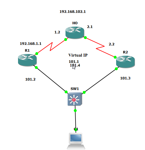 |
| Terminology |
R1 (config) #int fa0/0
R1 (config-if) #ip add 192.168.101.2 255.255.255.0
R1 (config-if) #no shut
R1 (config-if) #int s0/0
R1 (config-if) #ip add 192.168.1.1 255.255.255.0
R1 (config-if) #no shut
R1 (config) #router ei 100
R1 (config-router) #no auto
R1 (config-router) #network
0.0.0.0
Ho (config) #int fa0/0
Ho (config-if) #ip add 192.168.102.1 255.255.255.0
Ho (config-if) #no shut
Ho (config-if) #int s0/0
Ho (config-if) #ip add 192.168.1.2 255.255.255.0
Ho (config-if) #no shut
Ho (config-if) #int s0/1
Ho (config-if) #ip add 192.168.2.1 255.255.255.0
Ho (config-if) #no shut
Ho (config-if) #router ei 100
Ho (config-router) #no auto
Ho (config-router) #network
0.0.0.0
R2 (config) #int fa0/0
R2 (config-if) #ip add 192.168.101.3 255.255.255.0
R2 (config-if) #no shut
R2 (config-if) #int s0/0
R2 (config-if) #ip add 192.168.2.2 255.255.255.0
R2 (config-if) #no shut
R2 (config-if) #router ei 100
R2 (config-router) #no auto
R2 (config-router) #network
0.0.0.0
Ho #sh ip route
R1#sh ip int br
R2#sh ip int br
Now we will provide the IP add to the PC, which is
192.168.101.10. And computer Gateway would 192.168.101.1.
Right now 192.168.101.1 (computers default gateway) doesn’t
exist anywhere.
Computer #ping 192.168.102.1
Unsuccessful
Now we will provide this virtual ip
R1
(config) #int fa0/0
R1 (config-if) #standby 1 ip 192.168.101.1
R2
(config) #int fa0/0
R2 (config-if) #standby 1 ip 192.168.101.1
(Here
1 means Group 1)
R1#sh standby
State
is active, Group 1, Hello 3 sec, Hold 10 sec
Virtual
Mac – 0.0.0.0:0c07:ac01
Preempt
disabled, Default Priority 100
R2#sh standby
Computer #tracert 192.168.102.1
Now here we will shut down the interface f0/0 of R1
R1 (config) #int fa0/0
R1 (config-if) #shut
R2 will immediately become active
Computer # ping
192.168.102.1
Now we will up the R1s f0/0
R1 (config) #int fa0/0
R1 (config-if) #no shut
R1#sh standby
Now we can see R1 is in standby mode. Now we will shut the
fa0/0 of R2.
R2 (config) #int fa0/0
R2 (config-if) #shut
R1#sh standby
Here we can see state is active.
R2 (config) #int fa0/0
R2 (config-if) #no shut
Now here we can see R1 is active, but we want to make R2 as
active. For that we will change the Priority.
R2 (config) #int fa0/0
R2 (config-if) #standby 1 priority 101
R2 (config-if) #standby 1
preempt
Here we increased the priority which was by default 100, and
then enabled preempt which will force the high priority router to become
active.
R2#sh standby
Active
Now if we want to make the R1 active then we increased the
R1s priority and enable the Preempt.
R1 (config) #int fa0/0
R1 (config-if) #standby 1 priority 102
R1 (config-if) #standby 1 preempt
R1#sh standby
Active
Now here what we can see if the R1s f0/0 would down then R2s
f0/0 would become active but if the R1s
S0/0 would down then what will happen? Data will move first on R1 and
then it will reach on switch, after that it will go on R2.
R1 (config) #int s0/0
R1 (config-if) #shut
Computer# tracert
192.168.102.1
Now here we want, if the R1s s0/0 is down then data should
immediately forward via R2.
R1 (config) #int s0/0
R1 (config-if) #no shut
R1 (config-if) #int fa0/0
R1 (config-if) #standby 1
track s0/0
All the command will run on LAN Link.
Here if the serial link will down then track will decrement
10 in priority.
R1 (config) #int s0/0
R1 (config-if) #shut
R1#sh standby
Priority 92 (10 decreased)
Computer# tracert 192.168.102.1
Now data will go directly via R2
R1 (config) #int s0/0
R1 (config-if) #no shut
R1#sh standby
Priority 102
R1#sh run config int fa0/0
Now here if we want load balancing
R2 (config) #int fa0/0
R2 (config-if) #standby 2 ip 192.168.101.4
R2 (config-if) #standby 2 priority 101
R2 (config-if) #standby 2 preempt
R2 (config-if) #standby 2 track s0/0
R2#sh run int fa0/0
R1 (config) #int fa0/0
R1 (config-if) #standby 2 ip 192.168.101.4
R1 (config-if) #standby 2 preempt
R1#sh run int fa0/0
R1 (config) #int s0/0
R1 (config-if) #shut
R2#sh standby
R1 (config) #int s0/0
R1 (config-if) #no shut
R1#sh standby
R2 (config) #int s0/0
R2 (config-if) #shut
R1#sh standby
R2 (config) #int s0/0
R2 (config-if) #no shut
Computer# tracert
192.168.102.1
----


No comments:
Post a Comment